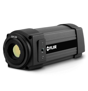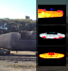
The Torpedo Car Monitoring System of Automation Technology is a turn-key solution for automatic Breakout-Early-Warning to guarantee plant safety. Trough the use of FLIR thermal imaging camera systems, our monitoring system allows a reliable assessment of the remaining lifetime of the refractory lining by monitoring the torpedo cars during operation.
System Tasks
Generally, the maintenance intervals for refractory material are determined based on experience. For safety reasons, these time intervals are commonly quite conservative. However, Flir thermal imaging cameras mean an alternative solution for determining the torpedo car condition because the external surface temperature is a reliable indicator of the condition of its refractory lining. The number of heats can thus be maximized without any safety issues and the re-lining can be scheduled more precisely. Considering the high costs for refractory maintenance, the system can significantly contribute to a reduction in the production costs of steel.
Torpedo Car Monitoring System
Usually, the thermal imaging camera from FLIR is placed in robust housings and located in fixed positions where they have a clear view of a filled cement mixture as it passes by on the torpedo car. Those cameras capture video images of the torpedo car in real-time and calculate temperatures over the torpedo’s wall surface. A few cameras can cover the entire surface of the torpedo, but typically a few regions of interest (ROIs) are predefined for closer scrutiny and analysis. The thermal images of ROIs where failures are more likely to occur can be stored in PC memory for later comparison to current images. Defining ROIs also allows FLIR’S IR Monitor software to ignore high temperatures on objects around the torpedo wall that are within the camera’s field of view (FOV), which in turn lowers the number of unwanted alarms.
These thermal video images and corresponding temperature data are carried over Ethernet and fiber optic cables to the industrial PC, which avoids problems from the electrically noisy mill environment.

The IR Monitor software can then compare each image frame from a camera to the image templates stored in PC memory. This gantry crane operator does not have to stop the crane at any particular location to capture images and the production can continue smoothly. When there is a match between the template and the corresponding portion of a camera’s FOV (i.e. one or the ROIs), temperatures are calculated. If the temperature exceeds the torpedo’s predefined parameters, an alarm is triggered. The exact parameter temperatures for alarms can be adjusted easily, based on mill experience.
The torpedo car monitoring system will automatically recognize predefined regions of interest (ROIs) and compare the measured temperature with previously set parameters.
Alarmingly high temperatures
The alarm could be just a warning if the temperature isn’t too high, and the movement of the cement through the torpedo car can continue. The operator can then compare the warning temperature to a trend analysis done by the software to determine if the torpedo can remain in service for another pour.
If its temperature is above a critical level, however, an emergency alarm will be triggered which will immediately stop the gantry crane movement. Also, alarm messages and images can be sent to a mill manager’s office via Ethernet, email, or FTP.
Typical Setup
The schematic illustration on this page depicts a typical setup for an automated Torpedo Car Monitoring System using the FLIR Camera. Although the analog video and digital I/O outputs from this camera allow it to operate as a standalone smart sensor, most steel mill applications use its digital data stream, sent over Ethernet lines, in computer-controlled automation systems. The Camera’s Ethernet interface can supply the camera’s video signal to virtually anywhere and facilitates monitoring from multiple locations.
FLIR’s IR Monitor software is used to control all camera functions, collect temperature data, display thermal images, and perform data analysis. The operator’s display is the primary interface for alarm functions.
